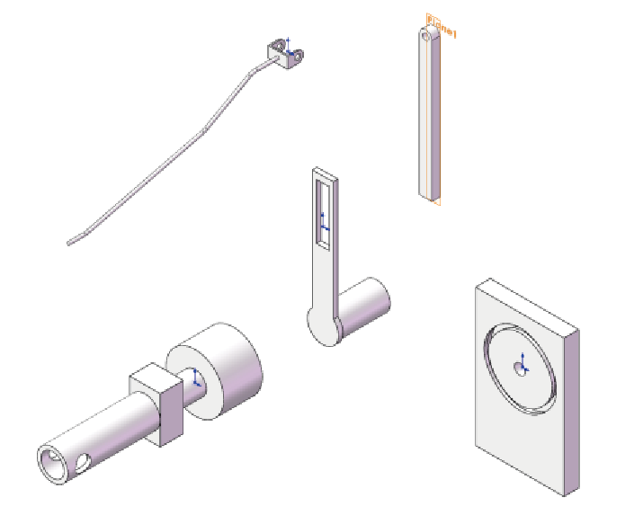
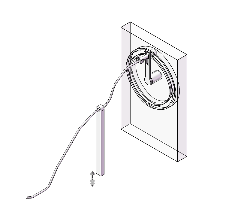
Prototype 2 in Solidworks
It is still the same lever idea but this time I want to make a nice track so that when it rotate, the shaft could stay at its own track.
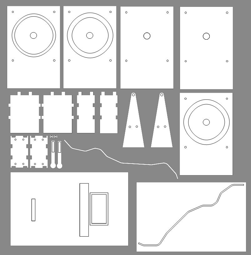
Lasercutting drawing
I ordered lasercutting servis using Taobao and the thickness is 3mm. This is the drawing.
connectors
I also use these connectors to try to make the rod have freedom while its connection to the track can always be perpendicular to the track surface.
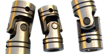
I also use bearing inside the track so as to reduce all the possible frictions.
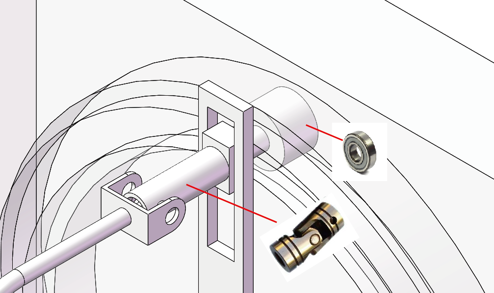
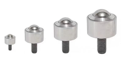
I also use this at the end of the connector to reduce friction.
Why fails?
I am sorry because I did not take a picture of this prototype although I assemble it. Because it fails, so I did not take any picture.
No matter how I tries, it would never be smooth. I realize this kind of movement can only be achieved when the track is horizontal so the distribution of the gravity would be even. Therefore, there would not be additional friction add to the side wall of the track. However, because I am using this lever to get a movement I want, I do not want the movement to be moving in XY plane. So I realize I need to totaolly change the mechanism.
Conclusion
I learn a lesson that the simulation from Solidworks would not work at all when it comes to physical things.
I need to totaolly change the mechanism.